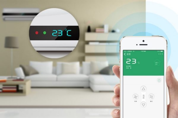
Do You Need an Automatic Temperature Control System Smart Home Circuit Diagram According to the different control loops, PID temperature controllers can be divided into two types: single-loop and multi-loop. A single-loop temperature controller can only have 1 input and 1 output, and is generally used to control 1 temperature point.
Controller (PIC) based automatic temperature control system is applied to upgrade the functionality to embed automation feature. to the temperature falls below the specified limit. The system monitors the temperature from the thermocouple temperature sensor, where it will control the electric heater according to the setting values in the

Automatic Temperature Control System Using Arduino Circuit Diagram
Establish the Target Temperature: To set the Target Temperature, utilize the controller's interface to set your desired setpoint temperature - this is what the controller will maintain over time. 2. Adjusting PID Parameters: PID parameters (Proportional, Integral and Derivative) need to be set appropriately to attain optimal control. The major parts of the feedback control system are built into the Temperature Controller. A feedback control system can be built and temperature can be controlled by combining a Temperature Controller with a controller and temperature sensor that are suitable for the controlled object.

In an increasingly automated and technologically advanced society, the capacity to regulate environmental elements such as temperature is crucial. Automatic temperature control systems are essential for maintaining ideal operating temperatures for equipment, guaranteeing comfort in living areas, and managing processes in industrial settings LM35 Temperature Sensor: Connect the VCC pin of the LM35 to the Arduino's 5V pin, GND to ground, and the output to the analog pin A0.This sensor will send temperature readings to the Arduino. Heating Element: Connect the positive terminal of the 12V power supply to one of the terminal of the heating element.Connect the other terminal of the heating element to the drain of the MOSFET

How to Use a PID Temperature Controller Step Circuit Diagram
Temperature sensor LM35 and Arduino Uno are the hardware used interfaced with computer, and the temperature is controlled in the room. Automatic temperature control system is an important