Regenerative Braking Applied to a Circuit Diagram There are two circuits in the hydraulic circuit of the regenerative braking system: the driving circuit and the drain circuit. The driving circuit includes a two-position four-way valve in addition to a cartridge valve, which is a one-way valve. The secondary component uses a pump or motor to direct the flow of oil from the reservoir to the

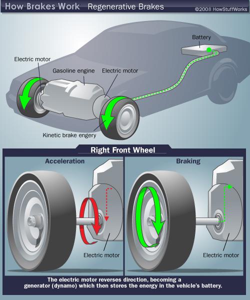
Mechanism for regenerative brake on the roof of a Škoda Astra tram The S7/8 Stock on the London Underground can return around 20% of its energy usage to the power supply. [1]Regenerative braking is an energy recovery mechanism that slows down a moving vehicle or object by converting its kinetic energy or potential energy into a form that can be either used immediately or stored until needed.
PDF Regenerative Braking of BLDC Motors Circuit Diagram
Where Regenerative Braking Isn't Used. Trains have a lot to gain from recovering kinetic energy, but they typically don't, even though they have magnetic brakes. Instead, the braking circuit disperses energy in a bank of resistors above the carriages. This energy is lost as heat into the atmosphere as current flows through the resistors. Regenerative braking is implemented in conjunction with anti-lock braking systems (ABS), so the regenerative braking controller is similar to an ABS controller, which monitors the rotational speed of the wheels and the difference in that speed from. one wheel to another. In vehicles that use these kinds of brakes, the brake controller not only monitors the speed of the wheels, but it can
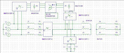
regenerative braking starts. •The peak current from simulation is around 0.5Amps @ 70% duty cycle. This translates to 24V * 0.5 Amps = 12 Watts. Since brake force is proportional to the current, this is the point of maximum brake force. •Beyond that point, the current starts to fall, mainly because of the motor construction (resistance and regenerative braking system on a BLDC motor using a Buck-Boost converter with micro control, which will serve as an electric car braking mechanism. Figure 1. Regenerative brake block schematic . Figure 2. Regenerative brake diagram . 2. Research Methodology The objective of designing this regenerative braking circuit is to streamline the device
What Is Regenerative Braking? Its Diagram and How it Work Circuit Diagram
Regenerative braking slows down the vehicle by utilizing kinetic energy of the rotating wheels to charge the battery of the vehicle. Continue reading to know more about its principle, construction, and working. In this article, we're going to discuss: What is regenerative braking system? 1.1. Working principle:
